
Collaborating with a steel joist engineer or manufacturer early in the life of a project can help prevent cost-overruns and shorten project timelines. An architect’s vision can often be achieved with less expensive products and systems that are quicker to install—if only the right questions are asked.
Engineers of record (EORs) are generally risk averse—and rightly so. But much like the way a general practitioner MD and a specialist MD both are highly qualified doctors, an EOR might not have the same depth of knowledge of joists and decking of a steel joist engineer.
Being open to ideas out of engineers’ and architects’ comfort zones—such as using higher-strength grades of steel for decking that allow for a thinner (lighter) gage deck and simplifying engineering complexity—might shorten project timelines and contain total project cost.
“For example, EORs will sometimes specify unnecessary moments of inertia,” says Kurt Voigt, New Millennium Building Systems engineering manager. “Moments of inertia can increase member weight considerably because they drive chord sizes for the joists or girders. We have found on many occasions, the moments of inertia that were specified really were not required or were over-specified. They could have been reduced considerably, which saves money.”
Moments of inertia are most often specified related to the stiffness of a roof relative to deflection and ponding.
“Concerning water on the roof, for example, the EOR needs to make sure the roof is not going to get too much of a bowl effect that would cause water to pond, progressively increasing the weight supported by the roof and eventually causing a collapse,” Voigt says.“
Ponding is a legitimate cause for specifying moments of inertia. But sometimes EORs use assumed or estimated moments of inertia in their structural models in order to analyze the behavior of the overall structure. Those moments of inertia are sometimes then specified in the bid and design documents, and many times are not accompanied by a note that lesser values may be permissible. In such cases, the joist manufacturer would provide a joist or girder that meets the specified moment of inertia but may be considerably heavier than what is required to resist the design loading.
“EORs should be risk-averse, but if they talk to us during the design phase, we can provide them information to make better assumptions or estimates early in design, which allows them to have a handle on the relative cost impacts early in design,” Voigt says.
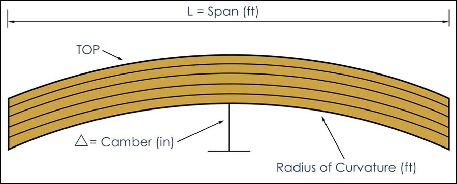
Another example of over-specification potentially leading to added project costs is deflection and camber. When EORs are designing a partition load, such as a curtain wall or something heavy hanging off the joist, they often will specify a deflection limit for the joist carrying those elements.
“The deflection limit is generally pretty stringent, and it’s usually not clear to us under what load combinations or load categories we need to be looking at the deflection,” says Anthony Reid, joist detailer for New Millennium.
In the absence of specific direction, the project may end up with a much heavier joist than necessary. “We may combine the partition loads with other specified loads that the EOR didn’t intend for the deflection check because we don’t have anything from them permitting different combinations,” Reid says.
“In addition, camber in the joist essentially arches the joist upward and may help offset some of the deflection,” Voigt says. “We are steel joist professionals and can provide specific deflection and camber information. If deflection limits of 1 inch are specified, with just a little clarification—such as if it’s 1 inch below a horizontal line, 1 inch below where the joist starts cambered with no applied load or if it’s 1 inch below top of joist after all dead loads are applied—we may discuss the use of camber with them, saving the project money.”
Similarly, snow drifts are often specified around rooftop units (RTUs).
“When we have a square mechanical air conditioning unit on a roof, the EOR needs to look carefully at the specifications for snow drift requirements all around those units in accordance with ASCE 7-10. Section 7.8 indicates ‘If the side of a roof projection is less than 15 feet long, a drift load is not required to be applied to that side,’” Reid says.
“On one project, when we looked at the actual RTUs, we were able to save the customer approximately $70,000 while still remaining within the code,” Voigt says. “We are very familiar with roof design because that’s what we’re working with every day for thousands of projects every year, and some specifying engineers may be relying on design software that doesn’t account for the exceptions, such as automatically applying a drift load around an RTU even if it’s unnecessary.”
Another area of over-specification that often leads to unnecessary costs is large weld sizes specified on chord toes or on chords attaching to columns or tie plates. Weld size can drive material thickness.
“For example, if a 3/8-inch fillet weld at 4-inches long is specified on the bottom chord of a joist with 5/16-inch thick chords, we’d have to bump it up to be 7/16-inch thick just to receive that weld,” Reid says. “To save money, they could specify a smaller weld that is longer. Instead of a 3/8-inch weld, they could specify a ¼-inch weld. That ¼-inch weld only has to be 50 percent longer to be the same strength and would use 33 percent less welding material.”
“Having a conversation with the joist manufacturer about chord thickness and weld size early in the project can save time and money,” Voigt says. “No one wants to be surprised when we have to increase chord thickness because of weld size that may put us overweight and require changes.”
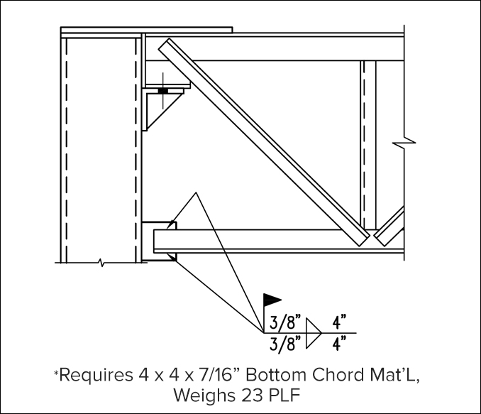
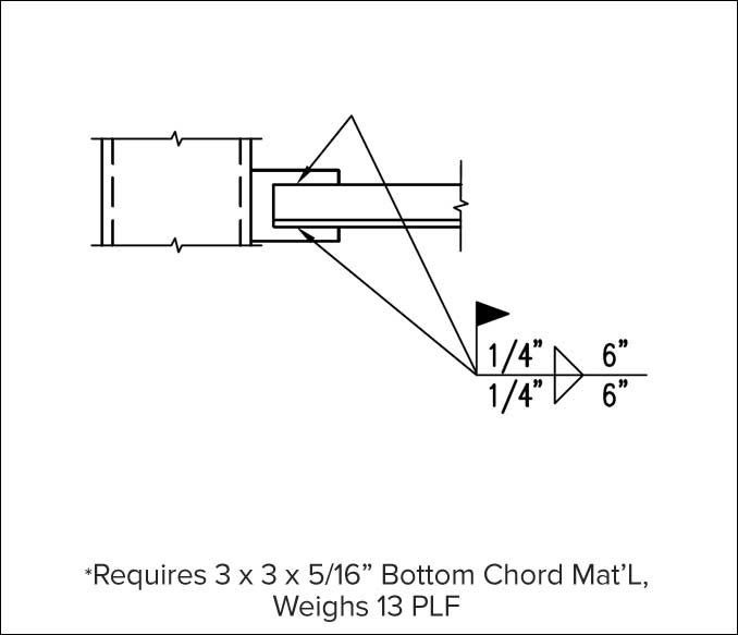
A change in weld size on this drawing saved the project money by reducing the amount of steel required on the chord receiving the weld.
The same is true of end moments. Without clarity in the drawing about the direction and category of the moments, the EORs risk a steel joist engineer interpreting their intent.
“We had a project where we were provided a table that listed moment values, and our interpretation of how they were being applied ended up being totally different than the engineer’s intent,” Voigt says. This resulted in nearly $160,000 in rebuild costs that could have been saved if the drawing had indicated all of the intended combinations of loads and end moment locations.
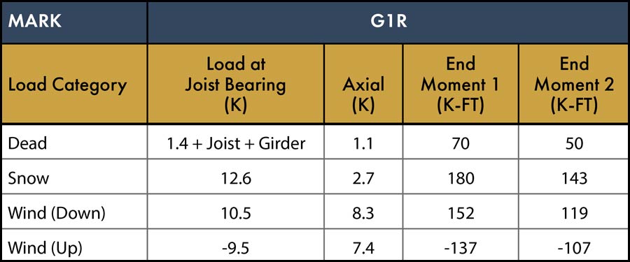
To avoid potential rebuild costs, diagrams and notes should clearly indicate to which ends the moments apply and in what combination(s) instead of relying on joist engineers’ interpretation. In this case, the joist engineers were later instructed to apply end moment 1 to one end, and end moment 2 to the opposite end, and then vice versa, in any combination with the other category moment loads.
The benefits of early project collaboration and clear communication with a steel joist engineer is a time and money saver. Everyone involved in the project has the same goal: use the best materials to achieve the architectural vision while providing adequate safety and reducing project cost and erection times. This can be achieved by using all the resources available at the time of specification, especially bringing in the joist experts.
Proper fall arrest anchorage specification protects workers and controls costs. This often is done incorrectly. On structural steel framing projects, fall arrest anchorage and screen posts are often field-attached to the top of a steel joist chord. Posts welded to thin chord angles, which act independently, can be problematic. There are two solutions to consider.
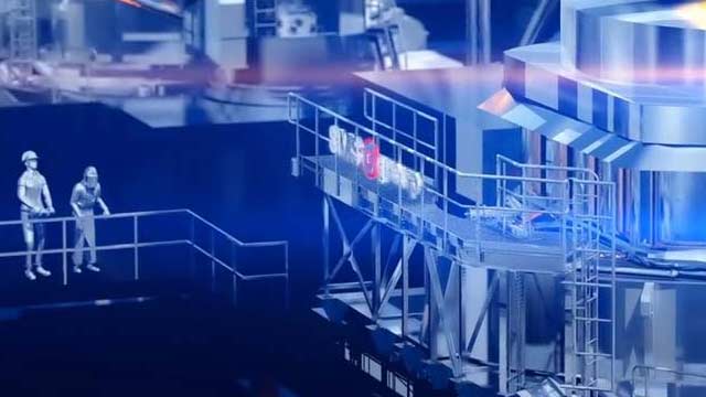
Hundreds of massive joist girders and thousands of standard steel joists are required to achieve the grand scale of the new, $1.9 billion Steel Dynamics Inc. steel mill in Sinton, Texas. It will be the most technologically advanced steel mill in the country and the largest project SDI has ever undertaken.
Building a better steel experience
